
FHDRM Undergoes Qualification Testing Before Being Fielded in Armored Vehicle Fleet
With over 25 years of experience designing and building rugged electronics for use in the Aerospace and Defense industry, DSE is well-experienced in validating product qualifications through third-party laboratories. In fact, these tests and DSE’s own validation methods are critical in demonstrating the reliability of DSE products before fielding a new program.
In 2021 DSE was contracted by a leading defense vehicle OEM to support a wheeled armored vehicle fleet. Understanding the program’s need to provide the warfighter with digital, high-definition detail, DSE customized its FHDRM 10” and 15” models to include CANBus and discrete inputs/outputs, as well as to support a custom application programming interface. By leveraging its existing product sub-assembly designs, DSE quickly produced a customized solution that would support its partner’s technical needs, while also withstanding the extreme conditions experienced on the battlefield.
With the proper solution in place, it was time to move on to extensive MIL-Spec testing. Keep reading to see how the FHDRM displays performed when put through rigorous testing, simulating the conditions outlined in MIL-STDs 810, 1275, 461 and more.
Putting FHDRM to the Test
In the defense world, rugged electronics must operate every time to ensure mission safety and success, and subjecting electronics to the extreme conditions experienced in the field is critical for establishing reliability and operational performance.
Both of the program’s customized FHDRM displays were put to the test against a range of procedures and then inspected for damage, defects or failure.
Temperature
Defense electronics must be prepared to meet a variety of extreme conditions throughout their lifecycle. MIL-STD-810G provides specific guidance on the wide range of temperatures these rugged electronics could encounter to ensure their integrity, safety and performance. As part of these third-party tests, the FHDRM units were subjected to the following procedures.
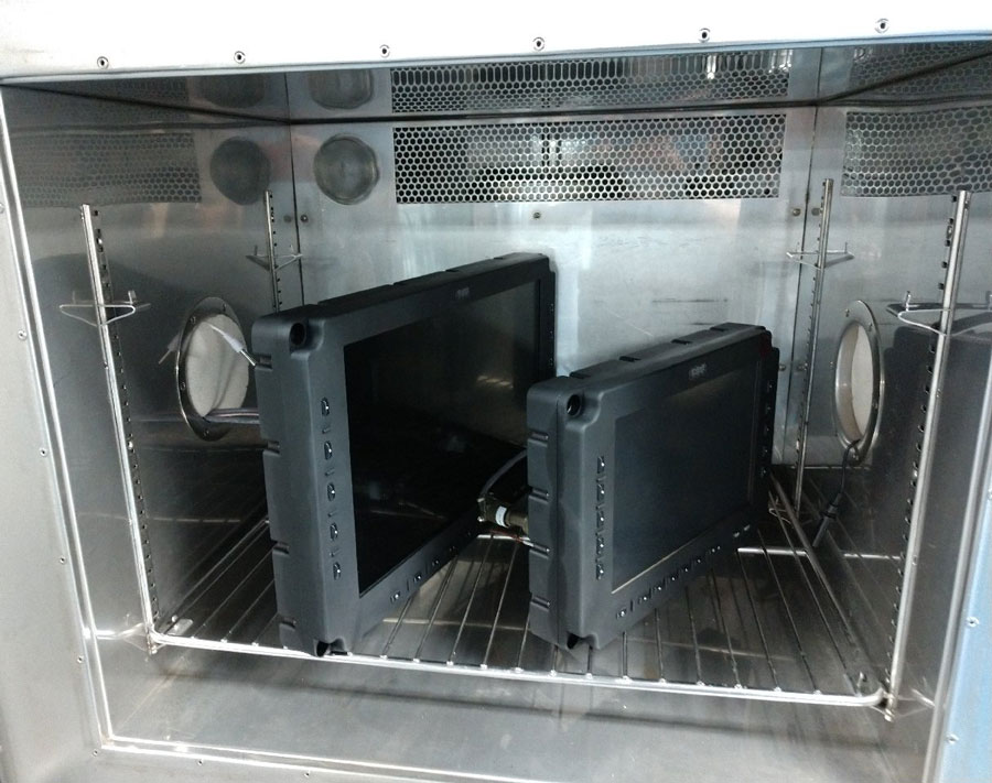
High Operating Temperature Test | MIL-STD-810G, Method 501.5, Procedure II
FHDRM’s performance was tested after exposure to the A1 operating condition of 49°C/120°F.
With each FHDRM unit placed inside of a temperature chamber, they were powered on continuously during three days of testing. During this time, a technician would intermittently perform interactive functions with the displays’ bezel keys, and communication channels while evaluating video performance. At the end of the testing period, both devices were evaluated, and no anomalies or failures were noted.
High Storage Temperature Test | MIL-STD-810G, Method 501.5, Procedure I
The FHDRM displays were again tested for their high-temperature endurance, this time against the A1 storage condition of 71°C/160°F.
Both units were placed inside the same temperature chamber while powered off. The chamber was heated to full temperature and the displays were left for seven days unprotected. Once the test was complete, both FHDRM displays passed their full acceptance test procedure.
Low Operating Temperature Test | MIL-STD-810G, Method 502.5, Procedure II
To demonstrate the FHDRM’s integrity during low temperatures, it was exposed to conditions of -32°C/-25°F following a Basic Cold Profile (C1).
At the start of the procedure, both displays were placed in the chamber and stabilized for four hours at -32°C before being powered on. The units were then tested for an additional two hours, with a technician interacting with the display halfway through the procedure. In their final temperature test, the FHDRM units again passed inspection after returning to ambient temperature.
Impact
It’s no surprise significant impact on a standard display would likely lead to catastrophic failure, but in the world of rugged electronics, withstanding the extreme is paramount to the mission. In order to test the FHDRM display’s against common in-field occurrences, a series of impact procedures were administered with the same evaluation standard; breakage constitutes failure.
Boot Impact
Under the requirements of the boot impact test, the displays must not be damaged by the impact of six strikes to the center of the surface by a 45lb pendulum. The pendulum, which is required to be released at an angle of 20° ± 2°, must also not exceed 0.5 square inches and is to be covered with cowhide leather with a thickness of 1/8 ± 1/64 inch. This test emulates the possible strike of a soldier’s boot to the glass face of the display.
Once the pendulum was configured as outlined in the requirements, it was released for a total of six impacts to each display, unprotected. Each display was tested independently and emerged from the test without any glass breakage.
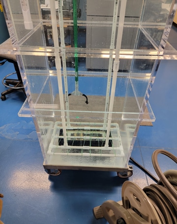
Wrench Impact
Similar to the boot impact test, the requirements of the wrench impact test require the display to withstand six impacts to its front surface. This time, the impacts were administered from a two-ounce steel ball with a 0.94-inch diameter that was dropped from a height of 20 inches.
A guide tube was used to align and release the steel ball, which impacted the FHDRM in separate evaluations. After the test was completed, both units successfully moved on to the next procedure.
Sharp Point Impact Test
In the last of the impact tests, the FHDRM displays were required to demonstrate their ability to remain functional after the impact of a sharp conical steel point with a tip diameter of 1.0 mm and impact energy of 0.65 in-lbs.
Again the guide tube was used to release a ball bearing to strike the steel point resting on the glass surface, and the procedure was repeated a total of six times. At the end of each test, the FHDRM units did not experience any breakage and successfully passed functional testing.
Shock & Vibration
Methods 516.6 and 514.6 of MIL-STD-810G outline the procedures a device must undergo to understand its ability to withstand mechanically induced shocks and vibrations that are typical of rugged environments and defense applications. This set of procedures ensures that materials do not fail or degrade as a result of the simulated environments and that the device remains operational.
Functional Shock | MIL-STD-810G, Method 516.6, Procedure I
The functional shock procedure tests a device’s ability to withstand exposure to shocks that can typically be encountered during handling and vehicle operation in the field. Following this procedure, both FHDRM units were subjected to 18 total shocks each among the following three positions and durations:
- Vertical axis, 25 g for 6.0 msec duration;
- Longitudinal axis, 18 g for 2.8 msec duration; and
- Lateral axis, 19 g for 4.4 msec duration.
Both displays successfully demonstrated their integrity without damage or degradation during the course of tests.
General Vibration | MIL-STD-810G, Method 514.7, Procedure I
Procedure I applies to devices deployed on ground vehicles to ensure that materials do not experience failure in performance or reliability after undergoing simulated vibration for a specific duration of time. During its third-party testing, FHDRM was subjected to MIL-STD-810G Method 514.7 Procedure I for a period of 16.1 hours for each of the three axes. Following a continual test, the FHDRM displays were successfully tested before proceeding onto the next axis.
Electromagnetic Compliance
MIL-STD-461F establishes the requirements for controlling electromagnetic interferences in Ground Army applications. Each method in the standard refers to specific limits and test procedures. Among MIL-STD-416F methods, both FHDRM units were tested against:
- Method CE102 | Conducted Emissions, Power Leads, 10 kHz to 10 MHz
- Method RE102 | Radiated Emissions, Electric Field, 2 MHz to 18 GHz
- Method RS103 | Radiated Susceptibility, Electric Field, 2 MHz to 40 GHz
Throughout all three test procedures, the FHDRM units successfully passed the requirements.
Voltage
MIL-STD-1275D outlines the voltage requirements necessary for electrical power systems deployed in military ground vehicles. These requirements cover a variety of conditions in which a system could experience surges, spikes or other disturbances. It is critical that devices meet these specifications in order to maintain operation and safety on the battlefield. During this set of procedures, the FHDRM displays were tested to four key segments:
Steady-state Voltage | MIL-STD-1275D, Section 5.1.4.1
During this procedure, the circuit steady-state voltage shall be applied between 23 VDC and 33 VDC.
Imported Voltage Spikes | MIL-STD-1275D, Section 5.3.2.3
Both polarities, positive and negative, are tested by inducing 50 spikes at one-second intervals. Failure is considered any damage that affects the components or normal operation of the device.
Imported Voltage Surges | MIL-STD-1275D, Section 5.3.2.4
This procedure begins with testing five 50ms pulses of +40V total amplitude from a source impedance of 20 mΩ in normal operating mode. Once complete, a second test of five additional 50ms pulses of +100V total amplitude from a source impedance of 500 mΩ to simulate generator-only mode.
Imported Voltage Ripple | MIL-STD-1275D, Section 5.3.2.5
Simulated ripple voltage is applied to the devices for a duration of one minute to demonstrate their ability to withstand the following voltage frequencies: 50Hz, 12kHz, 48kHz, and 200kHz.
Each FHDRM display was tested independently, and with failure representing deviation from normal operation, the units successfully maintained normal function and passed the series of voltage requirements.
Immersion
IP guides the protection rating against the ingress of dust and water. Per its partner’s requirements that both FHDRM units be rated IP67 (NEMA 6 Submersible), DSE submerged the FHDRMs in 1m of freshwater for a testing period of 30 minutes.
During their separate evaluations, each display was monitored closely for air bubble streams that would indicate a breach. At the end of each test, the displays were opened and inspected for water ingress. Both units passed without anomalies or failures.
Decontamination
During a decontamination test, a display must be functional without damage or degradation after exposure to a cleaning spray of hot/cold water.
With the units less than three feet away, a water stream with a nozzle exit pressure of 50 psi and a spray diameter greater than 1 in at the point of impact was applied. This water spray was applied for the duration of 1 min/ ft2 of surface area. Then, the nozzle exit pressure was increased to 105 psi with the same spray diameter and duration of 1 min/ ft2 of surface area.
In order to pass these procedures, both FHDRM units needed to demonstrate that they did not absorb water or suffer defects. In addition, soft surfaces must be resistant to chemical agent absorption and not suffer degradation as a result of exposure to chemical contaminants. Upon visual inspection and being weighed, both FHDRM displays passed the requirements without suffering damage or water ingress.
With qualification testing complete and both displays demonstrating their adherence to the program and MIL-STD requirements, DSE looks forward to fielding the FHDRM 10” and FHDRM 15” variants later this year.
These tests are part of our ongoing commitment to consistently manufacture high-quality products. Whether they are being tested in our own facility, a third-party laboratory or on the battlefield, DSE rugged electronics continually prove their ability to withstand the extreme.
Want to learn more about any of the test procedures in this blog, or simply have a question for our team? Contact us.