
MIL-STD-810: Environmental Testing Standards for Rugged Electronics
Today, we’re diving deep into MIL-STD-810, the set of methods and test procedures that have governed environmental engineering considerations for aerospace and defense applications for over 60 years. In this blog, we’re exploring why standards like 810 exist, the unique test methods that 810 encompasses in its 1,089 pages and why compliance is so important to establishing safety and program success.
Keep reading to learn more about:
Why do Military Standards Exist?
If you’ve worked in the aerospace and defense industry, even briefly, it’s likely you’ve come across military standards. These familiar names, MIL-STD-810, MIL-STD-461, MIL-STD-1275 and others are the benchmarks for not only ensuring standardization within the industry, but also for establishing the reliability, compatibility and operability of products and components developed for use in military programs
From programming languages, to communications and environmental conditions, military standards offer guidance on almost every facet of the defense world. In fact, the exhaustive list of military test methods even includes standards that offer guidance on the formation of military standards.
All of this goes to say that these comprehensive technical specifications improve operational efficiency and dependability, which on the battlefield means improved safety and mission success for our allied forces.
MIL-STD-810: Environmental Engineering Considerations and Laboratory Tests
MIL-STD-810 was first published in 1962 to establish environmental test methods for aerospace and ground equipment in areas such as temperature, vibration and immersion. Sixty years and now on revision H, this document still serves its original purpose of ensuring products can withstand the extreme environments and remain operationally compliant in defense applications.
MIL-STD-810 Test Methods
Today, MIL-STD-810H, released in 2019, includes an extensive series of methods that define how laboratory tests should be conducted to ensure a product meets its requirements. Products that demonstrate success when tested against each method, are then considered compliant with the standard—often a requirement for inclusion in certain military programs. The full list of test methods includes:
- 500 Low Pressure (Altitude)
- 501 High Temperature
- 502 Low Temperature
- 503 Temperature Shock
- 504 Contamination by Fluids
- 505 Solar Radiation (Sunshine)
- 506 Rain
- 507 Humidity
- 508 Fungus
- 509 Salt Fog
- 510 Sand and Dust
- 511 Explosive Atmosphere
- 512 Immersion
- 513 Acceleration
- 514 Vibration
- 515 Acoustic Noise
- 516 Shock
- 517 Pyroshock
- 518 Acidic Atmosphere
- 519 Gunfire Shock
- 520 Temperature, Humidity, Vibration, and Altitude
- 521 Icing/Freezing Rain
- 522 Ballistic Shock
- 523 Vibro-Acoustic/Temperature
- 524 Freeze-Thaw
- 525 Time Waveform Replication
- 526 Rail Impact
- 527 Multi-Exciter Testing
- 528 Mechanical Vibrations Of Shipboard Equipment (Type I – Environmental And Type II – Internally Excited)
For a detailed description of each of the test methods, keep reading below, or to skip ahead—learn more about how products are tested against each method.
Expanded Test Method Descriptions:
Method 500.6 – Low Pressure (Altitude)
This method determines whether materials can successfully (and safely) withstand low pressure and rapid pressure changes. These tests apply most directly to products used or stored in pressurized and unpressurized areas of an aircraft. Extremely fast pressure changes are simulated in 500.6 procedure III (rapid decompression) and procedure IV (explosive decompression). These two procedures focus on crew safety to ensure effects of a catastrophic airborne event are not worsened by equipment on board and further endanger personnel.
Method 501.7 – High Temperature
Throughout the temperature test methods, climatic conditions are used to define ranges for ambient and induced temperatures that materials are tested against. These design types, such as “Hot Dry”, mimic climate experiences across the globe. In this test method, a product’s short-term safety, integrity and performance is examined against the “Basic Hot” and “Hot Dry” climatic design types, which range from 30°C to 71°C.
Method 502.7 – Low Temperature
Much like the high temperature method, low temperature evaluates a material’s ability to withstand specific climatic conditions—this time ranging from “Basic Cold” to “Cold” and “Severe Cold.” Procedure I (storage), procedure II (operational) and procedure III (manipulation) tests range between -21°C and -51°C depending on the likely environment of deployment
Method 503.7 – Temperature Shock
This method examines the impact to a product’s performance and integrity when subjected to temperature changes of greater than 10°C. These sudden air temperature changes can represent a component moving from a climate-controlled area to extreme ambient conditions and are typically induced at a rate of 3°C per minute. Depending on the use case products may be tested to several cycles run concurrently.
Method 504.3 Contamination by Fluids
In this method, a material is exposed to contaminating fluid to determine whether or not exposure will result in failure. An extensive list of test fluids includes diesel fuel, antifreeze, lubricant and much more. Careful attention must be given during product design to ensure all porous and non-metallic parts are protected against these possible contaminants.
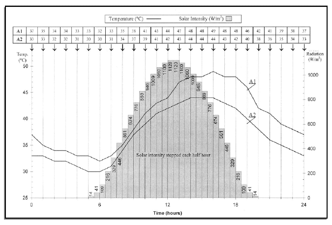
Method 505.7 – Solar Radiation (Sunshine)
The procedures in this test method evaluate the impact of the heating effects of solar radiation on a product and identify actinic effects of the exposure. This can present in the loss of seal integrity, fading of paint/plastic and failure of electronic components.
Method 506.6 Rain
This method tests a material’s ability to withstand rain without suffering damage as a result of leaking seals, cases or covers. Three procedures test conditions with specified speeds, volume and drip patterns.
Method 507.6 Humidity
In addition to having test methods dedicated to warm temperatures, MIL-STD-810 also addresses the humid conditions that are common in these environments. This method ensures that humidity, and resulting condensation, does not negatively impact any surface elements, electrical components and most importantly, functionality
Method 508.8 Fungus
It’s not uncommon, especially with natural materials, that some products may be susceptible to fungal growth, which can change the physical properties and function of a product. Spores from certain species of fungus are selected and the material is then exposed to the spores to allow germination. After a minimum of 28 days, it can be determined whether or not damage was experienced or if fungal growth persisted on the test unit.
Method 509.7 Salt Fog
For materials that will have significant exposure to environments with high levels of salt in the environment, Method 509.7 is recommended to determine the corrosive, electrical and physical effects of salt fog.
Method 510.7 Sand and Dust
Similar to how wet, humid and marine environmental conditions are simulated in the previous procedures, method 510 puts the dusty, sandy conditions often experienced in hot climates to the test. This method evaluates whether dust and sand each impact a product’s ability to operate properly, including the ability to transmit signals, its optical characteristics, penetration of seals and more.
Method 511.7 Explosive Atmosphere
This method applies to materials present on aircraft and vehicles where flammable vapors can originate from the equipment or an external source. It ensures that the product will not cause ignition or a burning reaction in fuel-air explosive atmospheres.
Method 512.6 Immersion
Immersion applies directly to how a material reacts when submerged in water. This method can be vitally important when testing electronics that can experience extreme environments or even amphibious applications.
Method 513.8 Acceleration
This method primarily relates to applications in aircraft and helicopters where quick acceleration, deceleration and maneuvers can result in damage to materials. Procedures in this method outline the proper movements and g level force to apply when simulating these conditions.
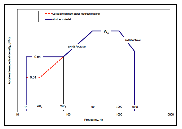
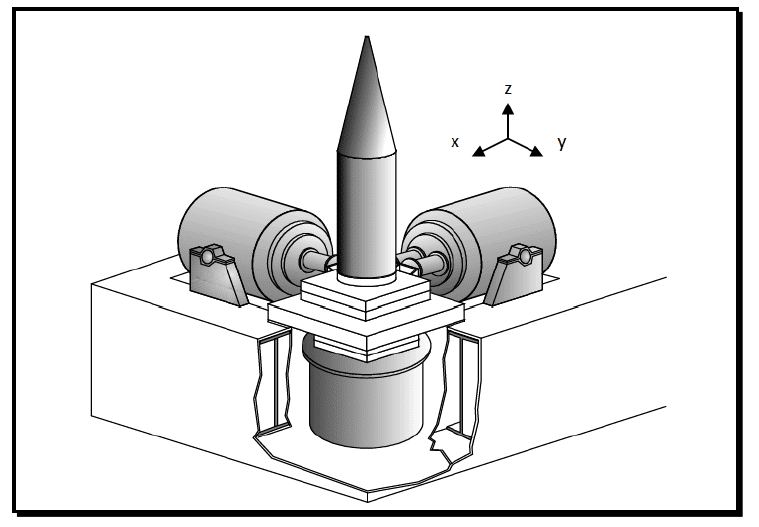
Method 514.8 Vibration
The vibration test method found in MIL-STD-810 determines whether or not vibration experienced throughout the life cycle of a product could result in physical or operational failure. The extensive procedures found in this standard apply to applications, such as fixed-wing aircraft, rotary aircraft, wheeled and track-wheeled vehicles.
Method 515.8 Acoustic Noise
The acoustic noise test method refers to simulating acoustic environments that generally cause airborne pressure fluctuations. In electronics, this can potentially result in wire chafing or fracture, as well as the loosening of small parts or cracking of components. Three test procedures simulate unique environments.
Method 516.8 Shock
In this test method, products are judged against their ability to withstand mechanically induced shocks that can occur throughout their lifecycle. According to MIL-STD-810, these mechanical shock environments are generally limited to frequencies of less than 10,000 Hz, with a duration of less than one second. Failure would be seen as any permanent damage, such as material fatigue, cracking, electronic malfunction and more.
Method 517.3 Pyroshock
Method 517 tests the ability of a device to withstand a pyrotechnic device being detonated near or on the device. This method observes whether or not the shock resulting from a detonation could cause damage or electronic failure.
Method 518.2 Acidic Atmosphere
Throughout MIL-STD-810, products are subjected to extreme environments and scenarios, and Method 518 is no exception. Acidic atmospheres can be present in industrial areas or near the exhaust of fuel-burning vehicles and devices, and the goal of Method 518 is to ensure that materials will not corrode or deteriorate in any way. To simulate these conditions, products go through a series of spraying periods using an acidic solution in a chamber, and are then stored before being inspected. The exact duration of the spraying periods and storage varies depending on the severity of the potential real-world exposure to acidic atmospheres.
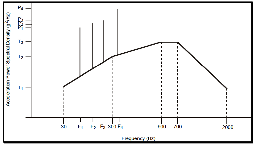
Method 519.8 Gunfire Shock
Similar to the previous test methods involving shock, method 519 involves testing a specific scenario where shock could potentially damage a product – in this case, as a result of gunfire. There are primary examples given in MIL-STD-810 when this might occur: as a result of airborne gun muzzle blast pressure, as a structure-borne shock transmitted through the gun mechanism or a combination of the two. Three procedures outline unique test conditions that monitor for signs of wear, material failure and electronic malfunction.
Method 520.5 Temperature, Humidity, Vibration, and Altitude
Upon first glance, method 520 may seem repetitive of earlier methods that cover temperature, humidity, vibration and altitude individually, however this unique test method combines all conditions in order to see the synergistic impact of adverse environments. Designed primarily with aircraft in mind, this method is geared mostly for electronic components and products that should be actively powered during testing. Despite covering a variety of unique conditions, this method is not a replacement for those that focus solely on one condition, such as temperature.
Method 521.4 Icing/Freezing Rain
The build up of ice can occur in a variety of conditions, from freezing rain to sea spray in cold environments. It’s the goal of method 521 to ensure these conditions do not negatively impact the operational capabilities of products. In one test procedure, products are placed in a temperature chamber at 0° C and first sprayed with cooled water, before lowering the chamber’s temperature to allow ice to harden. After a minimum of four hours, the product is examined for failure.
Method 522 Ballistic Shock
This test method covers a series of ballistic shock test procedures that evaluates a product’s ability to withstand shocks caused by a high level of momentum exchange. Its six procedures outline the shock frequencies and characteristics necessary to test devices dependent upon their weight.
Method 523.4 Vibro-Acoustic/Temperature
Method 523 combines testing conditions to determine the combined effect of vibration, acoustic noise and temperature on aircraft stores. This series of tests can identify defects, design weaknesses and more.
Method 524.1 Freeze-Thaw
While previous methods have tested the effect of heat, cold and ice, method 524 examines the unique scenario of transitioning between warm and cold environments while introducing moisture. In this test method, products are subjected to a variety of scenarios simulating thawing and freezing conditions with ice, condensation or moisture in order to determine if products become damaged as the moisture changes between a liquid and solid.
Method 526.2 Rail Impact
The durability of MIL-Spec electronics can’t be underscored, and method 526 truly puts that to the test by determining the ability of devices to survive railroad car impact conditions. This testing procedure not only looks for damage as a result of impact, but the potential of a device becoming a personnel safety hazard during collision.
Method 527 Multi-Exciter Testing
This method involves simulating a dynamic environment within the laboratory to put products through a combination of test factors.
Method 528 Mechanical Vibrations Of Shipboard Equipment (Type I – Environmental And Type II – Internally Excited)
MIL-STD-810’s Method 528 applies strictly to Naval shipboard equipment and tests both environmental and internally excited vibration to monitor for damage or defect.
MIL-STD-810 Testing Process
When a product is ready to be fielded for aerospace and defense purposes, typically a select set of test methods are determined depending on where the product will be integrated (such as a ground vehicle or a fixed-wing aircraft), the mission’s environment and expected operating conditions. The requirements, while governed by the MIL-STD, are somewhat flexible to allow for a more accurate determination of compliance for the particular application of the electronic system. It’s then time to validate that the selected product meets requirements.
For MIL-STD-810, and all military standards, testing is typically performed at a third-party laboratory. These certified laboratories ensure compliance with the exact procedures and provide a neutral position on the outcome of the validation tests. Some manufacturers, including DSE, can also provide in-house testing as an additional measure which many times will reduce costs, improve schedules, and allow more flexibility for unique requirements. For instance, DSE implements specific functional tests during vibration and temperature profiles that otherwise wouldn’t be possible at a certified testing house. DSE’s specialized engineering staff coupled with uncommon test analyzing equipment and monitoring software preclude a straightforward third-party test.
MIL-STD-810 Compliant Products
When choosing which products to include in a program, there are many factors to consider. Oftentimes, customers will look for MIL-STD compliant products to reduce expenses. Examining the MIL-STD compliance of a manufacturer’s products can help determine if a product would be suitable. Integrators can weigh the previous qualifications of a product, whether it was designed to meet MIL-STDs, an OEM’s experience and previous test reports to determine whether a product should be tested to certain methods and procedures.
Throughout this process, it is important to choose a partner that provides transparency and displays expertise in these areas. Several technical meetings and open conversations should be held to align on a product’s requirements and why it can reliably comply with the necessary standards. Finding a partner with experience qualifying products and with the proper knowledge of testing methods and procedures is paramount to ensuring a project’s success, goals and budget are achievable.
Nearly all of DSE’s MIL-STD product lines have been tested against MIL-STDs, including MIL-STD-810, for inclusion in aerospace and defense programs. These examples demonstrate just a sample of the unique testing conditions DSE products have undergone while validating their ability to comply with MIL-STD-810:

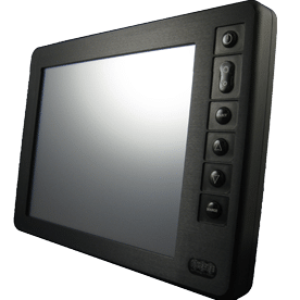
The HDRM rugged display is no stranger to qualification testing. Learn more here.
Gunfire Vibration – HDRM Rugged Display
The HDRM 9.0” display was selected for a high-profile, rotary aircraft application. As part of the qualification effort to standards such as 810, 461, 704, and DO-160, the EUT was required to pass a 3 axes gunfire vibration profile. Although the display would never be mounted to the chassis of the aircraft while in service and there were provisions for isolation mounts, the USAF requested frequency and acceleration values far in excess of general MIL-STD-810 operational vibration limits. The display was directly mounted to the shaker table and as a result of resonances, the vibration effect was amplified greatly. The product survived and operated through this demanding validation.
Explosive Decompression – MSM2 Rugged Display
The MSM212R display was installed as a mission computer interface aboard the B-52 aircraft. In addition to many MIL-STD-810 tests, such as high/low temperature, humidity, salt/fog, explosive atmosphere, immersion, acceleration, vibration, and shock, the MSM212 display was subjected to a challenging Explosive Decompression, Procedure IV test.
The test simulated the aircraft climbing from approximately 12,000ft above sea level to 50,000ft in 0.233 seconds which is equal to a rate of change of 32.0psi per second. Considering the MSM2 12.1” display is fully sealed to the IP67 standard, it must allow passage of air to occur in less than a ¼ of a second to avoid glass breakage and a potential danger to the crew members aboard. Through analysis the DSE team designed the product to pass this stringent and unique set of requirements. Read more about sealing considerations and advanced techniques on our blog.
MSM2, a staple in DSE’s suite of rugged military displays, was also used in a winning model of the US Marines Amphibious Vehicle Competition.
We covered FHDRM’s qualification testing for integration on both an armored fleet vehicle and a fixed-wing aircraft application on our blog.
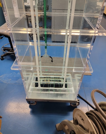
Immersion – FHDRM Rugged Display
In 2021 DSE was contracted by a leading defense vehicle OEM to support a wheeled armored vehicle fleet. DSE customized its FHDRM 10” and 15” models to include CANBus and discrete inputs/outputs, as well as to support a custom application programming interface, but before the two displays could be fielded, qualification testing was needed.
IP guides the protection rating against the ingress of dust and water. Per its partner’s requirements that both FHDRM units be rated IP67 (NEMA 6 Submersible), DSE submerged the FHDRMs in 1m of freshwater for a testing period of 30 minutes. During their separate evaluations, each display was monitored closely for air bubble streams that would indicate a breach. At the end of each test, the displays were opened and inspected for water ingress. Both units passed without anomalies or failures.
Final Thoughts
For over 60 years, MIL-STD-810 has established rigorous standards for quality and safety in aerospace and defense products. Manufacturers like DSE look to these standards when designing and building rugged electronics to withstand the most extreme environmental conditions across the globe.
Would you like to see more technical content like this piece? DSE regularly publishes “Behind the Build”, our look behind the processes that create rugged electronics. From sealing techniques to coatings, this series is developed with engineers in mind.